
This page is devoted to briefly summarize how the
different use-cases and scenarios are configured
through NFPA V2 (and above).
On the other hand, bear in mind that beside the pcap files, we
always provide a .nfo file (in the compressed archives of the pcap files)
where the different randomized header information can be found to script your VNF manually.
Note again that we also provide these pcap files using the already
defined packet sizes, i.e., they are available as 64-, 128-, 256-,
512-, 1024-, 1280- and 1500-byte packets.
In order to know which scenario-combinations are supported, i.e., for which
traffic traces the predefined flow tables exists, and how NFPA should be
configured to exploit this new feature, go to the
Walkthrough - NFPA control section.
IMPORTANT
Most of the use-cases below and their setup could be let to NFPA.
However, it is really important to emphasize that this is only possible
via setting the vnf_function functions properly (e.g., l2-switch), and
furthermore they only work with the Supported traces mentioned in each section below.
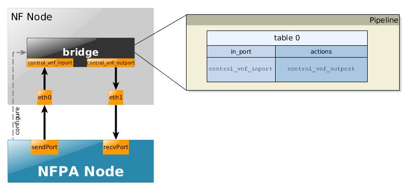
The bridge use-case is the most simplest scenario, it only receives packets from its
control_vnf_inport and immediately puts it on control_vnf_outport.
Accordingly, it works with all the traces.
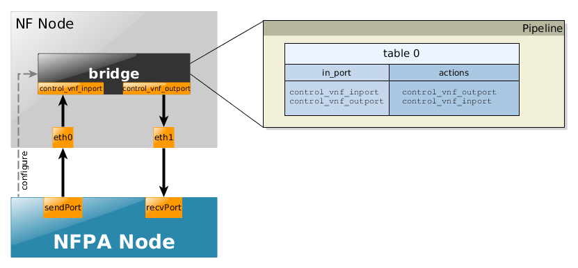
The exact pipelines for the uni- and the bi-directional cases could be found below.
- uni-directional
- bi-directional
Example to configure NFPA for OpenFlow control:
nfpa.cfg.nf_ctrl
      control_nfpa=true

      control_vnf=openflow

      control_path=/usr/bin/ovs-ofctl

      control_args=-O OpenFlow13

      control_vnf_inport=1

      control_vnf_outport=IN_PORT

      control_mgmt=tcp:192.168.22.2:6634
nfpa.cfg.traffic
      packetSize=64

      packetSize=128

      packetSize=256

      packetSize=512

      packetSize=1024

      packetSize=1280

      packetSize=1500


      trafficType=simple

      trafficType=trPR_12

      trafficType=trPR_24

      trafficType=trPR_36

      trafficType=trPR_48

      trafficType=trPR_100

      trafficType=trPR_1000


      #realisticTraffic=


      measurement_num=2

      measurementDuration=30

      sendPort=0

      recvPort=0

      biDir=0
nfpa.cfg.nf_data
      virtualization=no

      vnf_name=ovs

      vnf_version=2.7.0

      vnf_driver=kernel

      vnf_driver_version=4.11

      vnf_function=bridge

      vnf_num_cores=0

      vnf_args=

      vnf_comment=kernel driver autoscales to the available cores
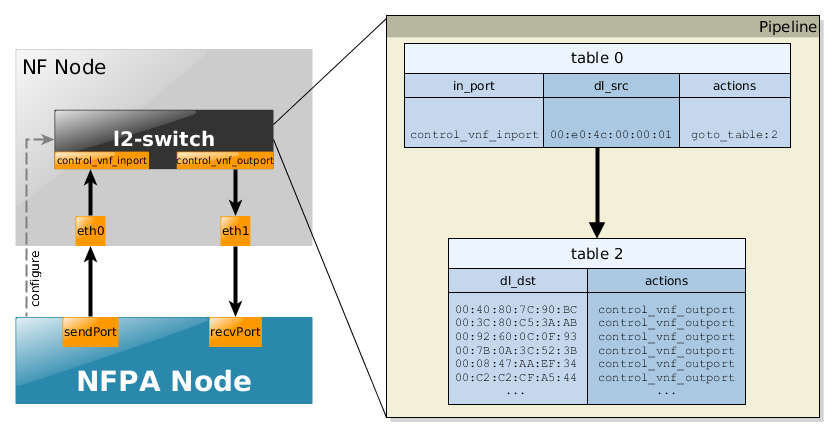
This scenario is trying to simulate how a real learning switch works except the fact that the "learning" part is already encoded into the flow tables. Accordingly, we briefly show the schemantics of the flow tables:
- table 0 consists of the incoming port and source MAC address information indicating the first "learning phase"
- table 1 contains the "learned" destination MAC addresses (that are typically known after the flooding procedures of one destination MAC address not existing in table 1.
Again, bear in mind that these flow rules are already installed, so there is no need for any learning procedures or separate controllers. For more information about how a learning switch works search for default controller application examples (like this or this).
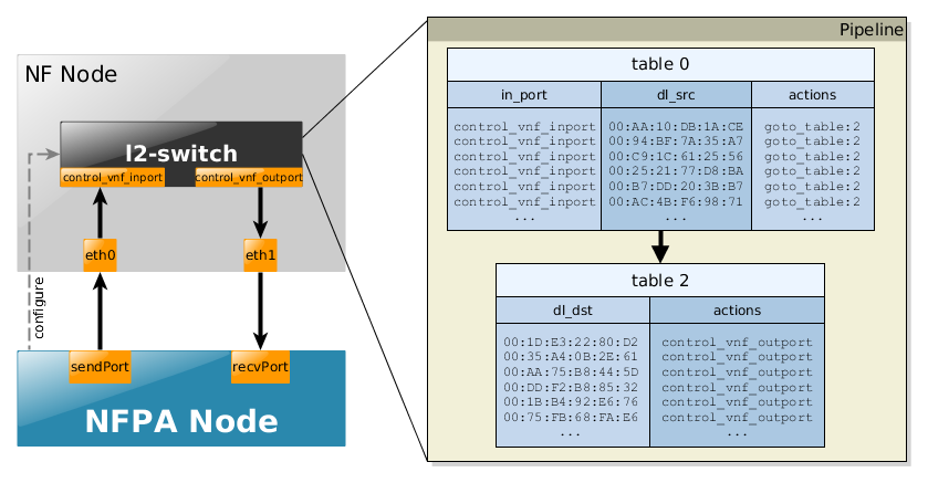
The use-cases, in particular, the flow tables and their sizes are a bit different according to the used trace. For instance, the traces, such as trL2, where the source MAC address is always the same, then in table 0 only one flow rule is present. In the following, we briefly summarize these scenarios via some snippets of the complete pipelines for all the supported traces.
Supported traces:
- trL2 - uni-directional
Example to configure NFPA for OpenFlow control:
nfpa.cfg.nf_ctrl
      control_nfpa=true

      control_vnf=openflow

      control_path=/usr/bin/ovs-ofctl

      control_args=-O OpenFlow13

      control_vnf_inport=1

      control_vnf_outport=2

      control_mgmt=tcp:192.168.22.2:6634
nfpa.cfg.traffic
      packetSize=64

      packetSize=128

      packetSize=256

      packetSize=512

      packetSize=1024

      packetSize=1280

      packetSize=1500


      trafficType=trL2_1

      trafficType=trL2_10

      trafficType=trL2_100

      trafficType=trL2_1000

      trafficType=trL2_10000

      trafficType=trL2_100000


      #realisticTraffic=


      measurement_num=2

      measurementDuration=30

      sendPort=0

      recvPort=1

      biDir=0
nfpa.cfg.nf_data
      virtualization=no

      vnf_name=ovs

      vnf_version=2.7.0

      vnf_driver=kernel

      vnf_driver_version=4.11

      vnf_function=l2-switch

      vnf_num_cores=0

      vnf_args=

      vnf_comment=kernel driver autoscales to the available cores
- trPR - uni-directional
Example to configure NFPA for OpenFlow control:
nfpa.cfg.nf_ctrl
      control_nfpa=true

      control_vnf=openflow

      control_path=/usr/bin/ovs-ofctl

      control_args=-O OpenFlow13

      control_vnf_inport=1

      control_vnf_outport=2

      control_mgmt=tcp:192.168.22.2:6634
nfpa.cfg.traffic
      packetSize=64

      packetSize=128

      packetSize=256

      packetSize=512

      packetSize=1024

      packetSize=1280

      packetSize=1500


      trafficType=trPR_12

      trafficType=trPR_24

      trafficType=trPR_36

      trafficType=trPR_48

      trafficType=trPR_100

      trafficType=trPR_1000

      trafficType=trPR_10000

      trafficType=trPR_100000


      #realisticTraffic=


      measurement_num=2

      measurementDuration=30

      sendPort=0

      recvPort=1

      biDir=0
nfpa.cfg.nf_data
    virtualization=no

    vnf_name=ovs

    vnf_version=2.7.0

    vnf_driver=kernel

    vnf_driver_version=4.11

    vnf_function=l2-switch

    vnf_num_cores=0

    vnf_args=

    vnf_comment=kernel driver autoscales to the available cores
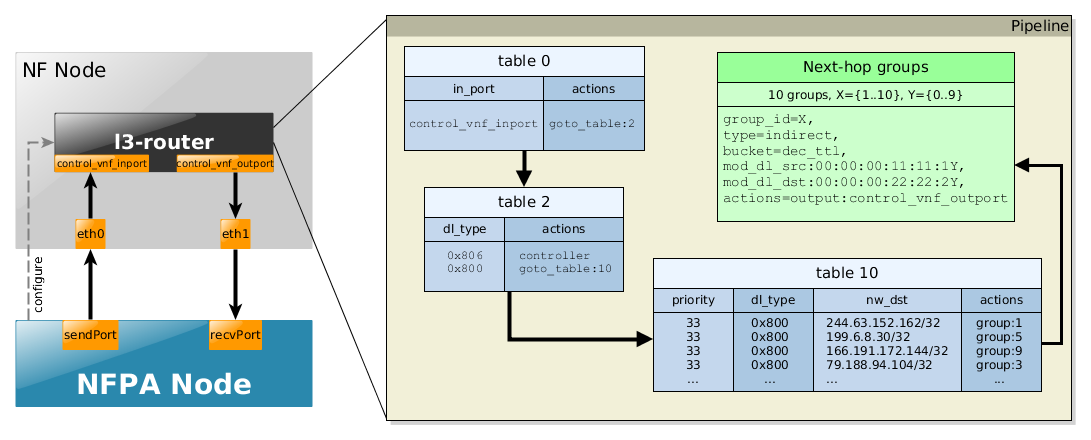
This scenario is trying to simulate how a real IP router works except the fact that forwarding merely via L2 headers are not part of the pipeline, just some catch-all rules are installed in some "pre-processing" tables. Accordingly, we briefly show the schemantics of the flow tables:
- table 0 would do the MAC learning part from l2-switch use-case, i.e., it would be filled with the in_port information and the source MAC addresses. Now, it just forwards the packets to the next table.
- table 2 would consists of the learned destination
MAC addresses found in the same subnet,
and would transfer such packets to the right output port avoiding the remaining part
of the pipeline.
Normally, it would process only those packets in the L3 pipeline where the destination
MAC address would be the MAC address of the router per se.
In contrast, now it processes each IP packet to the L3 flow table, and would send ARP packets to the controller. - table 10 consists of the IP addresses found in the traces. All IP match is set with /32 prefix and (prefix-num + 1 = 33) priority. Finally, a randomly selected group_id is set for each flow rule as an action.
- Last but not least, the groups consist of the real actions. Basically, they do the practical forwarding, moreover they also decrement the TTL field, while taking into consideration the lower-layer behaviors as well, i.e., they change the source and destination MAC addresses.
Extracts of the flow tables for the different traces can be found below, where the nfpa.cfg related parameters are used to ease the understanding.
Supported traces:
- trPR - uni-directional
Example to configure NFPA for OpenFlow control:
nfpa.cfg.nf_ctrl
    control_nfpa=true

    control_vnf=openflow

    control_path=/usr/bin/ovs-ofctl

    control_args=-O OpenFlow13

    control_vnf_inport=1

    control_vnf_outport=2

    control_mgmt=tcp:192.168.22.2:6634
nfpa.cfg.traffic
    packetSize=64

    packetSize=128

    packetSize=256

    packetSize=512

    packetSize=1024

    packetSize=1280

    packetSize=1500


    trafficType=trPR_12

    trafficType=trPR_24

    trafficType=trPR_36

    trafficType=trPR_48

    trafficType=trPR_100

    trafficType=trPR_1000

    trafficType=trPR_10000

    trafficType=trPR_100000


    #realisticTraffic=


    measurement_num=2

    measurementDuration=30

    sendPort=0

    recvPort=1

    biDir=0
nfpa.cfg.nf_data
    virtualization=no

    vnf_name=ovs

    vnf_version=2.7.0

    vnf_driver=kernel

    vnf_driver_version=4.11

    vnf_function=l3-router

    vnf_num_cores=0

    vnf_args=

    vnf_comment=kernel driver autoscales to the available cores
As in the previous use case, trPR traces can be used to simulate an L3 router scenario. Since VPP is not an OpenFlow software switch, its configuration needs to be done in a different way. Moreover, since it is (almost) a full-fledged (Cisco) router, traces should also be a bit special. In particular, in order to set up VPP as a gateway the destination MAC addresses in the traces should be the MAC address of the receiving port of the VPP. Furthermore, ARP entries are also needed to be configured.
Here, we show VPP was configured in our measurements, where the vnf_function for VPP was set to l3-router. The use case is depicted below.
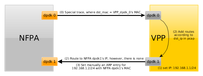
The steps are denoted by the arrows and their order is marked by the numbers on the arrows.
First, we created a similar trace to trPR traces with
the only difference that the destination MAC was fixed to our dpdk0
port's MAC address of the machine running the VPP.
In order to do this, just download the regular trPR traces, then modify
the destination MAC address via the trcreplay package.
# apt-get install tcpreplay
# cd /path/to/nfpa/PCAP/
# tcprewrite --enet-dmac=YOUR_VPP_INPORT_DST_MAC --infile=nfpa.trPR_100.64bytes.pcap --outfile=nfpa.trPR_100_MY.64bytes.pcap
Next, an IP address was set for dpdk1 interface, as it will be connected to the gateway, so all packets will be routed through this IP address. The command for this is (under the assumption that FortyGigabitEthernet1/0/1 is the dpdk1 interface):
# vppctl set int ip address FortyGigabitEthernet1/0/1 192.168.1.1/24
Next, we installed manually an ARP entry to VPP telling that the gateway, whose IP address is 192.168.1.2/24 (and is the recv_port of NFPA), has the following MAC address (For the best practice, know these information in advance before enabling DPDK on the interfaces).
# vppctl set ip arp FortyGigabitEthernet1/0/1 192.168.1.2 68:05:ca:30:50:75
Finally, add FIB entries according to the used trPR traces to be routed through the interfaces we configured above. You can use a simple for cycle again to this. Assuming you want to use your special trPR_12 trace, the command should look like this (Note again that the trace has to consist of the correct destination MAC address in each of the packets):
# for ip in $(tail -n12 trPR_12_customDST_MAC.nfo| cut -d ',' -f 4);
do vppctl ip route add ${ip}/32 via 192.168.1.2 FortyGigabitEthernet1/0/1;
done
Note that if the number of rules is more than 1000, then the above-mentioned command definitely lasts long. In these cases, it is better to use VPP's exec function, which waits for a file consisting of the commands. With this feature, installing 10.000 rules requires only seconds. To do this, modify the command above accordingly:
# for ip in $(tail -n12 trPR_10000_customDST_MAC.nfo| cut -d ',' -f 4);
do echo "ip route add ${ip}/32 via 192.168.1.2 FortyGigabitEthernet1/0/1"
>> install_10000_rules;
done
# vppctl exec /path/to/install_10000_rules
Now, if you start NFPA with your special trace, it should work. Just pay attention to the send_port and recv_port, as the send_port needs to be connected to VPP's dpdk0, and recv_port to VPP's dpdk1.
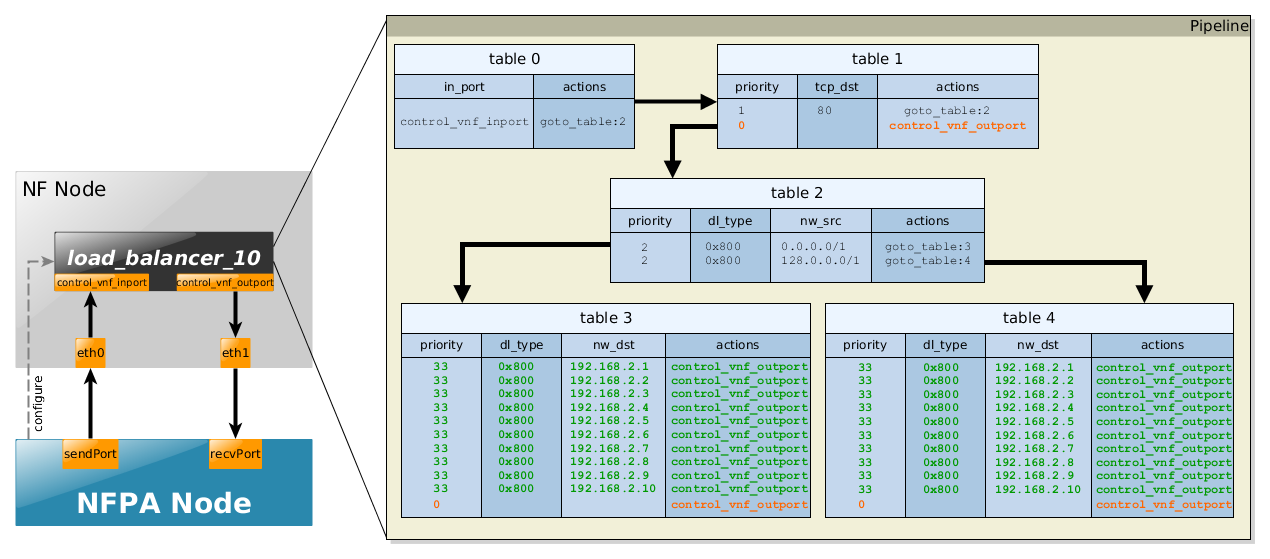
This scenario simulates how a simple load balancer works with an additional Access Control List (ACL). In particular, it balances the web traffic (port: 80) among the destined webservices based on the the source IPs. Next, we briefly show the schemantics of the flow tables:
- table 0 reads the packet from the control_vnf_inport.
- table 1 filters out every flow, which does not have TCP Destination port 80.
- table 2 redirects the incoming traffic into two further tables according to the source IP addresses. It is as simple as it could be - packets from the half of the IPv4 Internet goes to table 3, while the rest to table 4
- table 3 and table 4 take care of the final redirection, as they match the destination IP, i.e., the IP addresses of the web services, and pass the packets to them. Obviously, in reality table 3's output for a given destination IP would be another port, than table 4's output for the same destination IP.
Extracts of the flow tables for the different traces can be found below, where the nfpa configuration file related parameters are used to ease the understanding.
Supported traces:
- LB_ACL - uni-directional
Example to configure NFPA for OpenFlow control:
nfpa.cfg.nf_ctrl
      control_nfpa=true

      control_vnf=openflow

      control_path=/usr/bin/ovs-ofctl

      control_args=-O OpenFlow13

      control_vnf_inport=1

      control_vnf_outport=2

      control_mgmt=tcp:192.168.22.2:6634
nfpa.cfg.traffic
      packetSize=64

      packetSize=128

      packetSize=256

      packetSize=512

      packetSize=1024

      packetSize=1280

      packetSize=1500


      trafficType=LB_ACL_1

      trafficType=LB_ACL_10

      trafficType=LB_ACL_100

      trafficType=LB_ACL_1000

      trafficType=LB_ACL_10000

      trafficType=LB_ACL_100000


      #realisticTraffic=


      measurement_num=2

      measurementDuration=30

      sendPort=0

      recvPort=1

      biDir=0
nfpa.cfg.nf_data
      virtualization=no

      vnf_name=ovs

      vnf_version=2.7.0

      vnf_driver=kernel

      vnf_driver_version=4.11

      vnf_function=load_balancer_10

      vnf_num_cores=0

      vnf_args=

      vnf_comment=kernel driver autoscales to the available cores
Note that since this use-case is not an
exact-match use-case like most
of the previous ones, i.e., there is no flow rule for each of the flows,
there are low-priority catch-all rules
in order to count them to the final throughput data, too. These rules
are indicated with orange
color.
Another interesting fact to note is the rules
colored green.
We have defined 3 different load balancer
use-cases, where the number
of webservices N is in {1,10,100}.
The depicted pipeline above shows the case of
N=10. Thus,
if only 1 webservice is wished
to be considered then the vnf_function
itself is called load_balancer_1 and
in table 3 and table 4 of the pipeline, only 1 destination IP is
being catched (nw_dst=192.168.2.1).
Every other flow is going to match the low priority catch-all rule.
The case of 100 webservice could be easily imagined consequently.
The number of flows K in the corresponding
traces ranges from 1 to 100.000, in particular
K={1, 10, 100, 1000, 10.000, 100.000}.
Each combination of flows and use-cases are working, only different
amount of flows will be catched by certain flow rules.
For instance, (N,K)=(1,1000) means that the only one web service
could be destined, so a huge amount of flows from the trace
LB_ACL_1000 will be either filtered
out in table 1, or filtered out
later in table 3 or
table 4.
Final notes on the traffic distribution in the traces:
- K=1: 1 flow destined to 1 web service having IP address 192.168.2.1 (no RSS would work)
- K=10: 10 flows, 70% is destined to random web services (i.e., having TCP destination port 80, and destination IP from range 192.168.2.1 - 192.168.2.10), the remainings are randomly generated.
- K=100: 100 flows, 70% is destined to random web services (i.e., having TCP destination port 80, and destination IP from range 192.168.2.1 - 192.168.2.100), the remainings are randomly generated.
- K=1000: 1000 flows, 70% is destined to random web services (i.e., having TCP destination port 80, but destination IPs only range from 192.168.2.1 - 192.168.2.100), the remainings are randomly generated.
- The cases for the remining values of K are defined similarly.
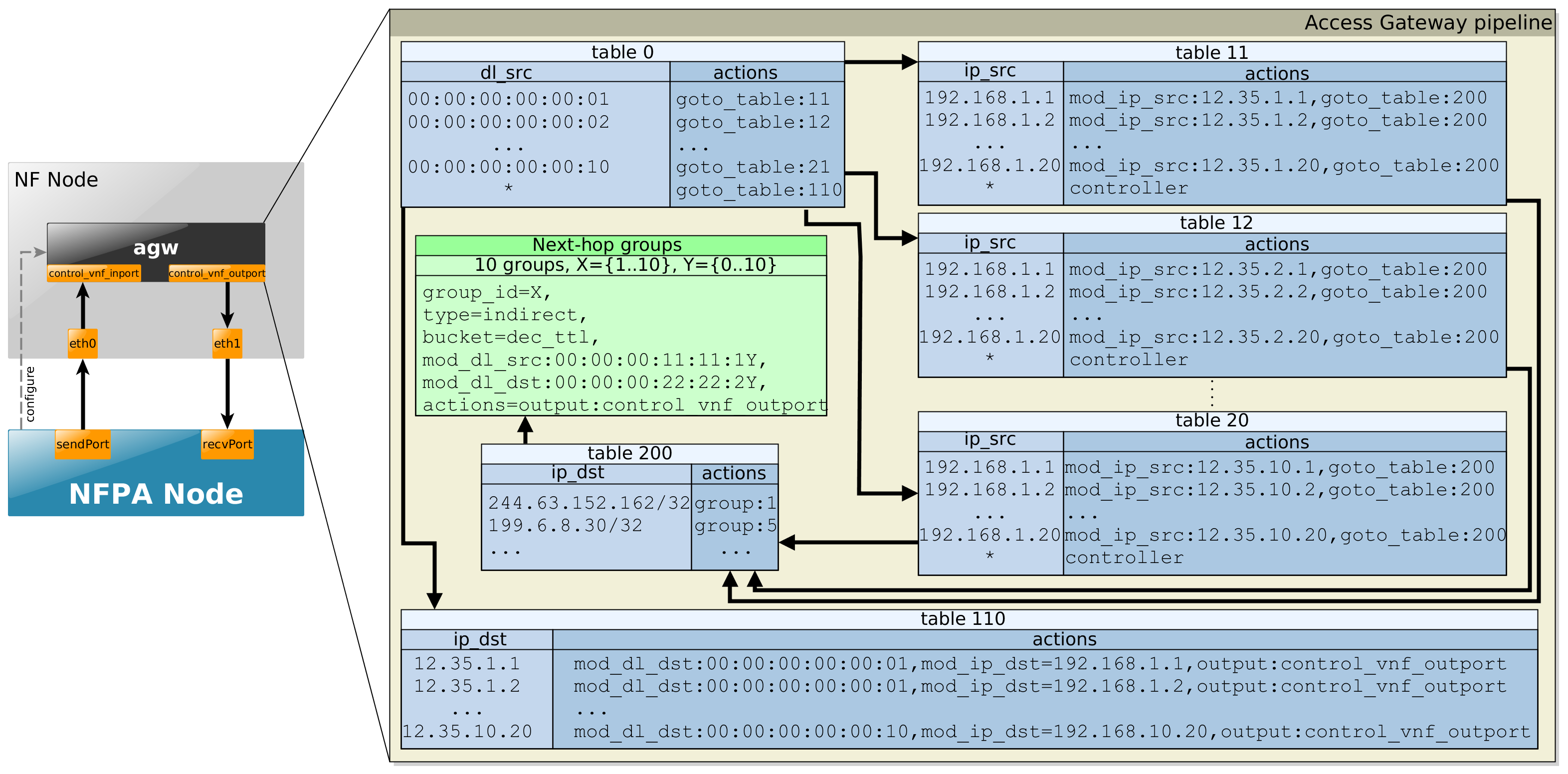
This telco access gateway is the most complex so far. The telco access gateway is the most complex so far as it consists of a Virtual Provider Endpoint (VPE) that serves Internet access to subscribers located behind CEs. For brevity, we identify CEs with the MAC address and we assume that the operator sets 10 CEs, each serving 20 users provisioned with a private IP address that is unique within the CE.
- table 0 separates user-to-network traffic on a per-CE basis from network-to-user traffic.
- user-to-network traffic goes to per-CE flow tables (table 11, etc.) that match the source IP address to identify the user and rewrite the source address to a unique public IP address (realizing a NAT), and finally to the IP routing table (table 200) that contains 10K random IP prefixes.
- network-to-user traffic goes to table 110 that matches on the destination IP to identify the user and the CE, swaps the destination IPs back to the private IP addresses, and then sends packets to the proper CE.
Supported traces:
- AGW - uni-directional
Example to configure NFPA for OpenFlow control:
nfpa.cfg.nf_ctrl
    control_nfpa=true

    control_vnf=openflow

    control_path=/usr/bin/ovs-ofctl

    control_args=-O OpenFlow13

    control_vnf_inport=1

    control_vnf_outport=2

    control_mgmt=tcp:192.168.22.2:6634
nfpa.cfg.traffic
    packetSize=64

    packetSize=128

    packetSize=256

    packetSize=512

    packetSize=1024

    packetSize=1280

    packetSize=1500


    trafficType=AGW_1flows

    trafficType=AGW_10flows

    trafficType=AGW_100flows

    trafficType=AGW_1000flows

    trafficType=AGW_10000flows

    trafficType=AGW_100000flows


    #realisticTraffic=


    measurement_num=2

    measurementDuration=30

    sendPort=0

    recvPort=1

    biDir=0
nfpa.cfg.nf_data
    virtualization=no

    vnf_name=ovs

    vnf_version=2.7.0

    vnf_driver=dpdk

    vnf_driver_version=17.02

    vnf_function=agw

    vnf_num_cores=2

    vnf_args=

    vnf_comment=nothing special
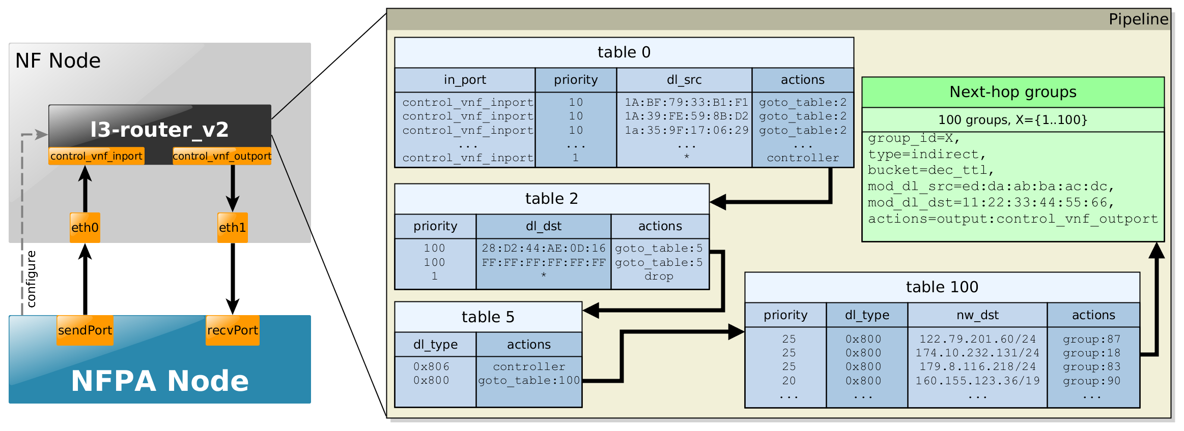
This scenario is an updated and a bit refurbished version of the plain l3-router above. As depicted in the figure below, it implements a full-fledged L3 router:
- table 0 would do the MAC learning part from l2-switch use-case, i.e., it would be filled with the in_port information and the source MAC addresses. Now, it is filled already according to the traces and it just forwards the packets to the next table.
- table 2 checks whether the destination MAC address is the current L3-router's
MAC address or the packets are broadcast messages in the L2 domain.
Observe that table 2 (with table 0) would implement the pure L2 switching part of the router, however in this case we still would like to measure the performance of the layer 3 parts (hence, table 2 consist only 3 rules, and in the corresponding trace the destination MAC is the same for all packets). - table 5 embodies a simple ARP filter.
- table 100 implements the actulal layer 3 routing part. In contrast to pure l3-router,
now the prefixes are neither /32, nor set randomly. They rather follow a recent analysis
found here
[Last accessed: 30/07/2017].
- Last but not least, the Next-hop groups consist of the real actions. Basically, they do the practical forwarding, moreover they also decrement the TTL field, while taking into consideration lower-layer behaviors as well, i.e., they change the source and destination MAC addresses.
Extracts of the flow tables for the different traces can be found below, where the nfpa.cfg* related parameters are used to ease the understanding.
Supported traces:
- trPR_v2 - uni-directional
Example to configure NFPA for OpenFlow control:
nfpa.cfg.nf_ctrl
    control_nfpa=true

    control_vnf=openflow

    control_path=/usr/bin/ovs-ofctl

    control_args=-O OpenFlow13

    control_vnf_inport=1

    control_vnf_outport=2

    control_mgmt=tcp:192.168.22.2:6634
nfpa.cfg.traffic
    packetSize=64

    packetSize=128

    packetSize=256

    packetSize=512

    packetSize=1024

    packetSize=1280

    packetSize=1500


    trafficType=trPR_v2_12

    trafficType=trPR_v2_24

    trafficType=trPR_v2_36

    trafficType=trPR_v2_48

    trafficType=trPR_v2_100

    trafficType=trPR_v2_1000

    trafficType=trPR_v2_10000

    trafficType=trPR_v2_100000


    #realisticTraffic=


    measurement_num=2

    measurementDuration=30

    sendPort=0

    recvPort=1

    biDir=0
nfpa.cfg.nf_data
    virtualization=no

    vnf_name=ovs

    vnf_version=2.7.0

    vnf_driver=dpdk

    vnf_driver_version=17.02

    vnf_function=l3-router_v2

    vnf_num_cores=1

    vnf_args=

    vnf_comment=nothing special
...no problem. In case of OpenFlow (currently no other API is supported),
the rules are not hardcoded into the source code, but they are rather
located in the of_rules/ directory.
Besides the fact that these files store
port information as metadata,
which are replaced during processing, the files themselves have a
special naming convention as the
traces have.
If one checks the of_rules/
directory, it quickly turns out how this convention looks like.
Let's have an example from one of the above use-cases.
The l2-switch use case, with trPR_1000 trace in an uni-directional
setting is defined in
l2-switch.trPR_1000_unidir.flows file.
On the other hand, if groups are
also required by the use-case (like l3-router above), a similar
file also exists, but with .groups
ending instead of .flows.
NFPA first uses the x.group files
if exist, then applies the .flows
files.
Thus, if you want to define your own use-case, say
my-case incidentally with
your own custom traffic trace
(for that naming conventions visit
Walkthrough page's Special PCAP section),
say my_trace, with your
desired directional setting (unidir or
bidir),
just create a file consisting of the flow rules and place it in
the of_rules/ directory, then name it
my-case.my_trace_unidir.flows.
When groups are also needed, place a similar file as well in
of_rules/ directory.
Furthermore, if bidir setting is
needed, then replace unidir to
bidir in the filename.
Last but not least, pay attention to port metadata conventions in
the files as the input_port and the
output_port is defined as
<INPORT1>
and <OUTPORT2>, respectively.
In case of bi-directional setup, use
<INPORT2> and
<OUTPORT1> additionally.
Sponsored by:
Contact: Levente Csikor (csikor_at_tmit_bme_hu), Mark Szalay (mark.szalay_at_tmit_bme_hu), Balazs Sonkoly (sonkoly_at_tmit_bme_hu), Laszlo Toka (toka_at_tmit_bme_hu)